Category Archives: CPN Pi-lot

This project is the documentation from building an integrated chart plotter with a microprocessor controlled autopilot using open sourced hardware and software.

Raspberry Pi Chartplotter Performance

There have been quite a few people interested in running OpenCPN forums (such as CruisersForum) and email lists. However a common criticism is that the performance is too slow.

I don’t find the Raspberry Pi to be frustratingly slow, but it is definitely slower than a modern PC. I compare it favorably to a low-end grayscale chartplotter/fishfinder currently on the market, but with a much larger full color screen. Everyone has a different tolerance for “slow” electronics,  so to that end I thought it would be worthwhile to create a video showing exactly what kind of performance can be expected.

I simply pointed my webcam at the screen to create the video below. There is no sound, and the camera had some difficulty with autofocus. It shows 5 minutes of OpenCPN running on my Raspberry Pi – from boot (power applied), through auto-launching OpenCPN, through GPS data acquisition. While waiting, I moved the chart around, zoomed in an out, and opened some other windows in the application. After letting the device sit for a few minutes, the utilization stabilized at around 10%. Hopefully, this can give everyone a good idea of what this low-powered and inexpensive device can do.

Autostart OpenCPN on Boot

Since this project’s main intent is to create a dedicated chartplotter/autopilot, it doesn’t make sense that I need to open a terminal window, start the gpsd service, and then double-click the OpenCPN icon on the desktop to get everything up and running. It should all just start up once the RPi boots up, and since it’s simply a Linux computer, this is possible, and really quite easy

First, the gpsd service needs to be started. As mentioned previously, there are a few terminal commands that are used to start the service. I simply created a pearl script in /etc/init.d/  that performs those steps:

#! /bin/sh
# /etc/init.d/startgps
#
### BEGIN INIT INFO
# Provides: 			noip
# Required-Start:		$remote_fs $syslog
# Required-Stop:		$remote_fs $syslog
# Default-Start:		2 3 4 5
# Default-Stop:			0 1 6
# Short-Description:	Simple script to start a program at boot
# Description:			A simple star/stop script
### END INIT INFO

echo 'Starting GPSD'
sudo service gpsd restart
sudo killall gpsd
sudo gpsd /dev/ttyAMA0 -F /var/run/gpsd.sock

exit 0

Then, I registered it to run at startup using the update-rc.d command. After a reboot, I was able to simply open a terminal window and execute xgps successfully, proving that the GPS stream was available.

The next step was to launch OpenCPN. I tried many different ways, but many had difficulties reading the user config settings. The simplest way, that worked great, was to create a launcher and place it in an autostart folder inside /home/pi/.config. The launcher file was already on the desktop, so it was a simple copy/paste process.

And with that, on reboot, OpenCPN launches, and after a minute or two GPS acquires the satellites and the chartplotter portion of the project is complete.

Resources:

Detailed Raspberry Pi Setup Documentation

This is the detailed documentation of every step necessary to create the Raspberry Pi chartplotter computer. I upsized my SD card to an 8-gig version so I could have more room for charts and other programs, and when I did so, I documented the process. This is the same process that was done before, but this time it is documented much more thoroughly.

Setting Up Raspberry Pi

  1. Format a new SD card.
    On my windows machine, I used the SDCard.org application as the OOB Windows format apparently doesn’t work (I didn’t try it, just going off of forum posts).The only option I changed was to set FORMAT SIZE ADJUSTMENT = ON and give the volume a name.
  2. Download the NOOBS package from raspberrypi.org and extract onto the SD card
  3. Connect the RPI hardware
    • HDMI connection to a monitor
    • Ethernet connection to a router with internet connectivity
    • USB Keyboard & Mouse
  4. Insert the SD card into the Raspberry Pi and boot. Install the OS of your choice (I used Raspbian)
    Confirm overwriting of the data
  5. On first load, set a few settings. I used the following:
    • Boot to Desktop: ON
    • Overclock: Medium (950MHz ARM, 250MHz Core, 2 overvolt)
    • Update internationalization for US
      • Raspberry pi is a UK product, set the Locale, timezone, and keyboard layout to the US versions.
    • Reboot
  6. It’s always smart to get the latest updates for the OS, so:
    • sudo apt-get update
    • sudo apt-get upgrade
  7. Next I want to set the video resolution to something fast, and yet of high quality. I settled on 1280×720@60Hz (720p CEA : Group 1, Mode 4)
  8. I also don’t want the screen to get turned off, since it’s probable that the chartplotter will run for long periods unattended. I found a forum post that fixed it, by editing lightdm.conf
  9. I want to use a wireless keyboard with built in trackpad, so the next step is to set that up
    • This was a very rigorous and difficult process that entailed inserting the USB dongle and turning on the power switch on the keyboard!
  10. Up to this point, I was using wired Ethernet for internet access. I don’t have a hub on the boat, so I got a wireless USB adapter to connect through instead. Setup was a 2-minute task:
    • Turn off the Pi
    • Plug the adapter into the Pi, and disconnect Ethernet
    • Reboot
    • Open the WiFi Gui
    • Click scan. double-click the network you want to connect to.
    • Enter WiFi password
    • Click connect
  11. Install Geany for C/C++/Python development
    • sudo apt-get install geany
  12. Enable I2C communication (for Arduino and sensors)
    • edit /etc/modules
      • add i2c-bcm2708 and i2c-dev
    • edit /etc/modprobe.d/raspi-blacklist.conf
      • #blacklist i2c-bcm2708
    • sudo apt-get install python-smbus i2c-tools

At this point I have a RPI device up and running.

Setup OpenCPN

  1. Rather than replicate the instructions, and to make sure that they stay up to date as new versions are released, I refer to the instructions at http://www.agurney.com/raspberry-pi/pi-chart  since that is line-for-line what I did to install OpenCPN
    • I did update config.txt for vector charts so that if I change my mind it won’t crash
    • I did update opencpn.config for MEMCacheLimit=40 NCacheLimit=10 (Must be done after running OpenCPN for the first time)
  2. Reboot
  3. Download the appropriate NOAA charts, and extract them into a directory
    • You can use Raster or Vector charts. I use raster charts as I think they look cool, and they seem to perform better on the Raspberry Pi
  4. Add the directory to the charts directory in OpenCPN, and allow them to be scanned and indexed
  5. As you zoom in and pan, more charts will be indexed and scanned. This takes a while on the RPI, but it seems to be pretty stable. Spend some time getting the most common areas in your cruising grounds stored, I simply pan, zoom, and wait until the charts are indexed. I took 3 iterations until I got all the charts indexed
  6. Install the Konni Logbook plugin from http://opencpn.org/ocpn/downloadplugins

References

Chartplotter/Autopilot Design Overview

Over the past few weeks I haven’t had much opportunity to work on this project, but I have tossed around some ideas.

I have found that the project is now complicated enough that I needed to mock up a design for what I plan to do. Here’s the current design, mocked up on Fritzing :
Design

This way I can make sure that the required (and desired) components would be available without needing to add expansion boards. For example, by doing this exercise, I have discovered that a future capability – to be able to consume AIS signals – would require additional components. Most likely in the form of a powered USB hub, but possibly as additional Arduino-based devices to save on power.

They Can Talk?

The next big hurdle in this DIY chartplotter project (which I need to name, because that’s too long to type), is to get the Raspberry Pi microprocessor to communicate with the Arduino motor control unit in the stern.

After talking to a few people, including Al Thomason (who has much more experience in Arduino and microprocessors than I), I have decided that the communication architecture will be NMEA 0183 over the I2C bus. I chose NMEA 0183 is a very easy, standardized messaging protocol, with many devices supporting it. It makes sense that this project, in the end, should be able to communicate with other devices. The new NMEA 2000 format has all sorts of political and copyright issues that I don’t want to deal with until it gets figured out by others. I chose I2C because it’s only 3 wires, and you can have over 100 devices on the bus (ignoring details like capacitance, interference, and device support). With a repeater, or something similar, the distances between devices shouldn’t be a problem either.

So, with that in mind, I decided to perform a test to see if I could get the Arduino device and the Raspberry Pi device to communicate with each other. For this test, the communication is going to be “backwards” – that is, the Arduino is going to send a message to the Raspberry Pi, rather than the other way around.

Borrowing heavily from pages on the web , I wrote a simple Arduino sketch that counts from 0 to 360 and back to 0 again, every second, infinitely, to generate a fake compass heading. I then generate an NMEA $HCHDG sentence with that heading inserted – once consumed by OpenCPN, the heading should slowly rotate around the compass rose back and forth. The code for the sketch is here:


#include <Wire.h>

#define SLAVE_ADDRESS 0x04
int heading = 0;
bool increasing;
String buffer;

/*
    Setup Method
*/
void setup()
{
    //Setup Arduino for I2C Slave
    pinMode(13, OUTPUT);
    Serial.begin(9600);
    Wire.begin(SLAVE_ADDRESS);
    Wire.onReceive(receiveData);
    Wire.onRequest(sendData);

    Serial.println("I2C Configured");

    //Setup communications
    buffer = "";
    increasing = true;
    heading = 0;

}

/*
    Loop Method
*/
void loop()
{
    //Get compass heading
    getHeading();

    //Send Compass heading message across wire
    sendData();

    delay(200);
}

/*
    Method to receive data across I2C Bus
*/
void receiveData(int byteCount)
{
    while (Wire.available())
    {
        char c = (char) Wire.read();
        buffer += c;
        if (buffer.endsWith("\r\n"))
        {
            Serial.println(buffer);
            buffer = "";
        }
    }
}

/*
    Method to send data across I2C bus
*/
void sendData()
{
    Wire.beginTransmission(SLAVE_ADDRESS);
    Wire.write(getNMEA());
    Wire.endTransmission();
}

/*
    Method to return current heading as an NMEA0183 HCHDG message
*/
char *getNMEA()
{
    char nmeastr[32] = "$HCHDG";
    char intStr[8];

    strcat(nmeastr, itoa(heading, intStr, 10));
    strcat(nmeastr, ",,,,");

    //Generate checksum
    int checksum = 0;
    for(int i=0; i&lt;strlen(nmeastr); i++)
    {
        checksum ^= nmeastr[i];
    }

    strcat(nmeastr, itoa(checksum, intStr, 10));
    strcat(nmeastr, "\r\n");

    Serial.println(nmeastr);
    return nmeastr;
}

/*
    Method to get the current compass heading
*/
void getHeading()
{
    //TODO: Pull from digital magnetometer device. Currently just makes up a heading
    if (increasing)
    {
        if (heading < 360)
        {
            heading++;
        }
        else
        {
            increasing = false;
        }
    }
    else
    {
        if (heading > 0)
        {
            heading--;
        }
        else
        {
            increasing = true;
        }

    }
    Serial.print("Current Heading : ");
    Serial.println(heading);
}

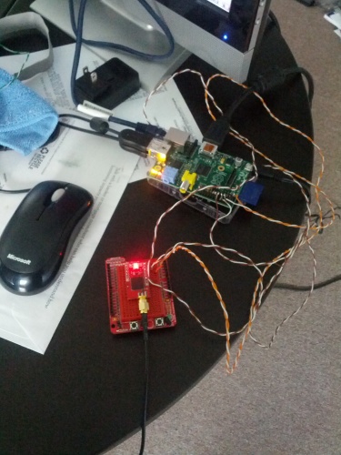
As for the physical connection between the devices, I decided to go with standard CAT-5 cable. I had a couple extra breakout boards for Ethernet jacks, so I wired those up directly to the SDA and SCL lines on both devices, using only three of the 8 wires available:

IMG_20130829_104530

Now, to see if they can talk.

References:

A DIY Chartplotter

It only took two evenings to get a Raspberry Pi chart plotter built out.

Yesterday I got OpenCPN up and running following instructions found on the web, and today I finished the process to the point that the hardware is a fully functional chart plotter.

The first improvement that had to be made was getting charts installed in OpenCPN. Thankfully NOAA provides free versions of nautical charts for US Waters and most frequented coasts regionally. It was simply a matter a downloading the appropriate charts (Washington State, and Region 15, Puget Sound) and unzipping them to a folder. I then added that folder to OpenCPN using the built-in options screen, and after a few minutes of compiling, the charts displayed.

IMG_20130821_174054

Then I needed to add GPS capability. First, I hacked together a few wires to an existing Venus GPS Module that I had from a previous Arduino project. This was a simple matter of soldering 3.3v power, ground, and TX/RX digital inputs between the items:

IMG_20130822_181042

Then I installed the GPSD service from the web, run the service, create a socket for it, and verify that the hardware is receiving the signal. Currently I need to hand-type this sequence each time I reboot the microcomputer: 
$ sudo service gpsd restart
$ sudo killall gpsd
$ sudo gpsd /dev/ttyAMA0 -F /var/run/gpsd.sock

Eventually this will be added to a script that will run on boot.

And then to test: 
$ sudo cgps
or
$ sudo xgps

And behold, signals from outer space:

IMG_20130821_191632

Now that all the pieces are in place, the final step is to add this GPS device to OpenCPN so that it can read the information:

IMG_20130822_180807

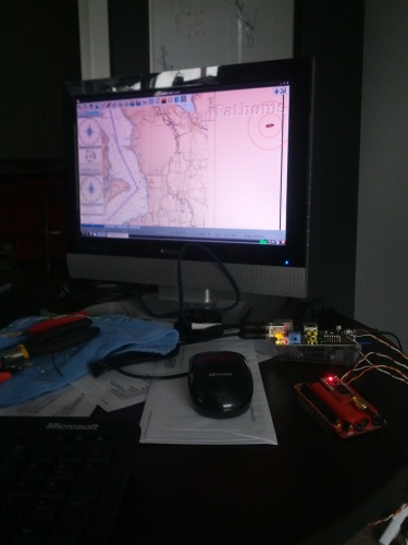
In this picture you should be able to see a rendered nautical chart of Puget sound, Heading, GPS satellite status, GPS location, and  Compass gauges on the left, and my “boat”, sitting off in Issaquah, since that’s where my GPS device is located.

It’s running at about 80% of the Raspberry Pi’s capability, at 1280×1024 with no overclocking.

And boom goes the dynamite.

It’s ALIVE!

My Raspberry Pi board showed up in the mail today. After a few minutes downloading and expanding the operating system, I got the machine up and running:

IMG_20130821_132454

Thanks to the very helpful walkthrough/tutorial at http://www.agurney.com/raspberry-pi/pi-chart , I now have version 3.2.0 of OpenCPN running on a brand new Raspberry Pi Model B. At this point I just have it up and running… No charts have been installed, GPS is not hooked up, there are no plugins installed, etc. But OpenCPN is clearly running:

IMG_20130821_143807

Meanwhile, on the Arduino side of the system, I was playing around with a 128×64 Graphic LCD screen that I had laying around. I plugged it in and found a library written for it that worked with very few changes. I doubt that the Arduino will actually drive an LCD, as it’s not in a convenient location to do so (down near the rudder post), but it was good to see that it worked regardless.

IMG_20130821_145943

Homebuilt Integrated Chartplotter and Autopilot

I’m going to try something bigger next.

My plan is to build an integrated chart plotter with a microprocessor controlled autopilot using open sourced hardware and software. That means, in the end, I should spend less than $500, total, for a fully functional autopilot and chart plotter.

Chart plotter Parts List

  1. Raspberry Pi
  2. OpenCPN
  3. GPS Module
  4. 10″ Display (by far the most expensive item)
  5. LCD display
  6. Controls (buttons, etc)
  7. Case/mounting

Autopilot Parts List

  1. Arduino ATMega 328
  2. Relay board
  3. Ethernet board
  4. Digital Compass
  5. Ethernet crossover cable

As far as implementation is concerned, at this point I have only done some basic research and tests.

I have already hooked up the existing hydraulic pump directly to a 12v source, as you can see below:

The next steps include:

  1. Installing OpenCPN on a Raspberry Pi device and getting that to run. Once installed on the boat, just that will be a nice addition, since I currently use a small PC hooked up to the inverter to power OpenCPN on board.
  2. Build an install a relay shield on my Arduino, and code it to keep a compass heading (I already have a 3-axis compass breakout).
  3. Build and add an Ethernet shield to my Arduino, and get it to communicate with Raspberry Pi
  4. Add a rudder angle sensor to the Arduino module, and display the information on the LCD screen in the cockpit
  5. Extract the NMEA messages (crosstrack, etc) from OpenCPN, and set that as the heading to hold on the Arduino module
  6. Have a drink and let the boat drive itself

There are of course additional features I am planning:

  • Configurable alarm to remind the “helmsman” to do a safety sweep
  • Connect GPS output to VHF radio for DSC service
  • Engine sensors (RPM, temperature, etc)
  • Cameras
  • TBD